

Research Article
Volume-1 Issue-1, 2025
Design of Robust and Optimal Controllers for Microgrid Power Control with Delays Between Power Plants
-
Received Date: March 05, 2025
-
Accepted Date: March 23, 2025
-
Published Date: March 30, 2025
Journal Information
Switch to Full Text Menu
Abstract
Today, as the population grows, the need for multiple power plants has increased to maintain control over the grid's power and frequency. On the other hand, in response to the increase in pollutants, efforts have been made to establish renewable power plants capable of producing power and reducing the amount of power produced by polluting power plants. This paper aims to examine three renewable power plant units and design a robust and optimal controller for a microgrid. The purpose of this study is to demonstrate that network dynamics are uncertain and that obtaining the optimal solution while consuming the least amount of energy is far more economically advantageous. Robust control is used to eliminate this uncertainty, and optimal control is used to achieve the optimum outcome. The 𝐻∞ robust controller is used in this paper to provide network resilience, and the optimal control is designed using the dynamic programming method, extracting the control signal. Because power control is easier to implement than frequency control and can also be used to control frequency, this study focuses on power control in the microgrid. Additionally, in the model intended for the microgrid in question, a delay exists between the power plant units.
Key words
Robust Control; Optimal Control; Microgrids; Delay; Power Control; Power Balance
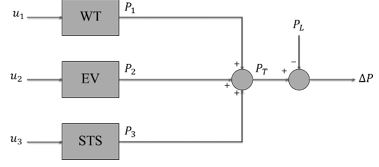 |
| Figure 1: Overview of the desired microgrid |
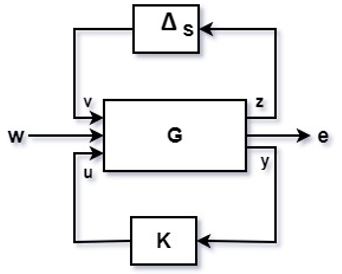 |
| Figure 2: Overview of the system's uncertainty block and controller location |
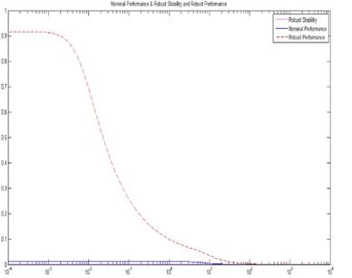 |
| Figure 3: Robust stability, nominal performance, and robust performance in the microgrid |
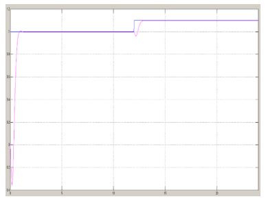 |
| Figure 4: The power balance in the network |
 |
| Figure 5: Control signals |
 |
| Figure 6: Changes in different system states |
 |
| Figure 7: Control signals |
 |
| Figure 8: Cost function changes in 24 hours |
Introduction
Today, one of the most pressing requirements of people is having access to clean air and energy 24 hours a day, with the least number of power outages possible. Population growth has resulted in an increase in pollution in cities, the most significant of which is related to power plants that utilize fuel and are forced to produce more power to maintain the network's power and frequency control, thereby increasing pollution. Renewable energy power plants are necessary to reduce air pollution and maintain network power balance; however, managing them and connecting them to the grid can be challenging. On the other hand, optimal utilization of each power plant unit is critical to achieving the best method of power generation during the day while maintaining network power balance [1-3]. As a result of these considerations, it is essential to use robust and optimal control to manage power in the network.
Numerous studies have been conducted in the field of microgrid power and frequency control; the most significant of which should be reviewed. In recent years, researchers have placed a premium on frequency control, employing various control methods. One of the studies examined the use of neural networks for frequency control, optimizing the networks through the use of highly innovative algorithms [4]. However, the article's primary flaw is that it ignores network uncertainty, and there is no delay between power plant units, which causes the network to become unstable in the presence of high uncertainty, a significant issue. Another type of controller that has been widely used in this field is the fuzzy controller. These controllers can effectively control the network's frequency and power using this controller and are one of the most efficient controllers that have received a great deal of attention [5]. Nonetheless, as with the previous study, the research overlooks the delay between power plant units and the uncertainty inherent in system dynamics, both of which can create several problems for the network.
A recent significant issue is that the majority of research has concentrated on network frequency control, even though power control, which is more straightforward than frequency control, can also be controlled. Several studies [6-15] demonstrate the same issue, but neither pay attention to network uncertainty or latency, necessitating the design of a robust controller in this paper. Due to the network delay and its effect on the system's behavior, and in order to obtain the optimal response, the optimal controller is also used, designed using the dynamic programming method.
The second section of the present study discusses the model for power control and the model for power plant units. The third section examines mathematical relationships relevant to the design of robust and optimal controllers. The fourth section examines the robust controller's output. The fifth section examines and analyzes the results obtained from both controllers and presents the optimal controller. The final section concludes the paper.
Modeling
This section first expresses the mathematical model for each power plant unit and then expresses the microgrid model when the delay is considered.
Wind Turbine (WT) Model
Since wind turbines employ a variety of control models, which are discussed in detail in other papers, the current study selected the first-order linear model. This model was developed using reference [14], and its conversion function is as follows:
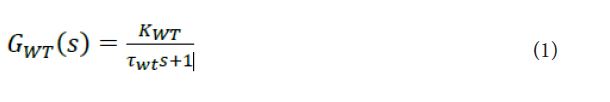
Where 𝐾𝑊𝑇 denotes the wind turbine gain and T𝑊𝑇 denotes the turbine time constant.
The wind turbine is the first renewable power plant unit, gaining considerable attention today. This function outputs the wind turbine's conversion power, and its input is the wind speed, which can be controlled via the wind turbine's gearbox.
Electric Vehicle (EV) Model
In developed countries, one of the newest technologies is the use of electric vehicles that can operate in various ways and can either power or receive power from the grid, where the accumulation of a large number of these vehicles can help balance the grid's power supply. The first-order linear model is used for this power plant unit, which is as follows [14]:
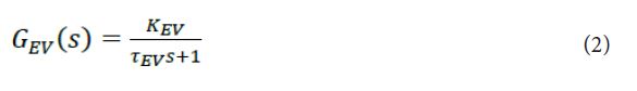
Where 𝐾𝐸𝑉denotes the EV gain and r𝐸𝑉 denotes the EV time constant. This function's output represents the EV's output power, and the battery charge level can control its input. Most countries are moving toward this technology, which will benefit car owners and create a balance of power in the network.
Solar Thermal System (STS) Model
This power plant unit utilizes several mirrors to concentrate sunlight and convert a liquid to steam, with the steam generated by the turbine used to generate power. Because this power plant unit is composed of four distinct components, each of which is a first-order function, its mathematical model is a fourth-order conversion function, as follows [14]:

Where 𝐾𝑟𝑒𝑓 denotes a refocus gain, 𝑟𝑟𝑒𝑓 denotes a refocus time constant, 𝐾𝑟𝑒𝑐 represents a receiver gain, 𝑟𝑟𝑒𝑐 represents a receiver time constant, 𝐾𝑔𝑜𝑣 denotes a governer gain, 𝑟𝑔𝑜𝑣 denotes a governer time constant, 𝐾𝑆𝑇𝑆 is STS gain, and 𝑟𝑆𝑇𝑆 is STS constant time. The output of this power plant unit expresses the STS unit's power, and its input angle can be adjusted using the mirrors.
Microgrid Model
The microgrid is powered by three non-polluting renewable power plants, and each of them has an input delay that reflects the communication delay between the power plants. This microgrid is depicted in Figure 1.
A delay of one second is used at the entrance of each power plant unit. This delay is expressed mathematically in Equation (4):
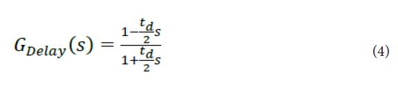
Where 𝑡𝑑 denotes the delay time.
As a result, the model of each power plant unit and microgrid were examined, and the mathematical relationships between each controller were expressed in the subsequent step.
Controller Relationships
This section discusses the mathematical relationships between controllers, beginning with dynamic programming relationships.
Dynamic Programming
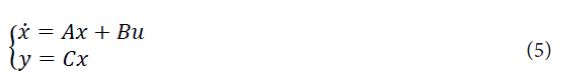
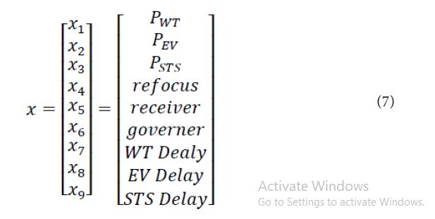
The mathematical models mentioned previously can also be expressed as a state-space model, as follows:
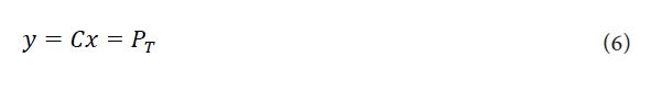
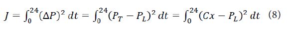
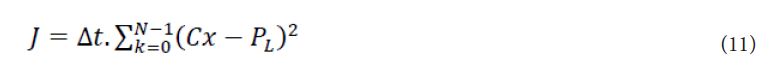
The dynamic programming method requires a cost function, and because the objective is to achieve network power balance, the cost function is defined as follows:
Since each system has several constraints, these constraints are expressed as follows:

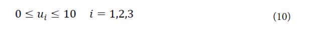
Normalization has been applied to these bands. Now that the first discretization is complete, the problem can be expressed as follows:

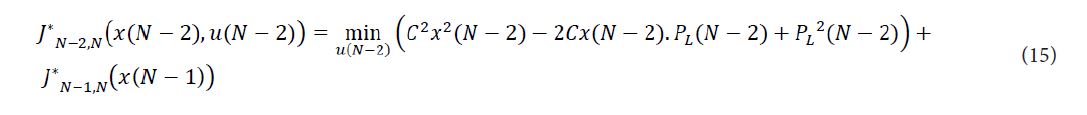
Hence, the u signal must be obtained backward:


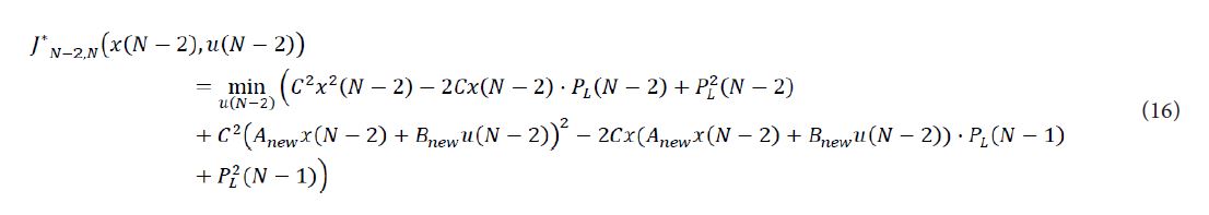
After deriving Equation (16) from the u signal, the result is obtained as follows:

Following that, repeat these steps until the end, and the final control signal is as follows:

Therefore, to satisfy the load and generate an appropriate control signal, the load must be predicted in advance and then used and placed in this context to produce the desired result. This control signal is used, and the following section performs the simulation.
Robust Controller
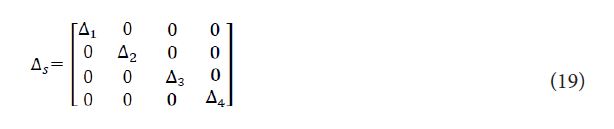
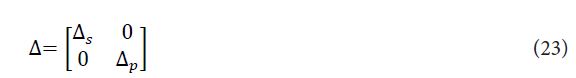
This section employs robust control relations, and as a result, a controller for this system is created. Because there is uncertainty in the dynamics of systems, in reality, the input and output of this system are considered uncertain, and the matrix of uncertainty is as follows:
The nominal system is stable and controllable, and three issues in robust control should be considered: nominal performance, robust stability, and robust performance. The following mathematical relations address these three issues:


The shape of each of the elements is as follows:
Δ is placed between input w and output e and is used for robust performance. Additionally, a high-speed and high- interest actuator must be considered in these simulations. Now, each of the blocks should be designed in 𝐻∞ robust control, and are expressed as follows:
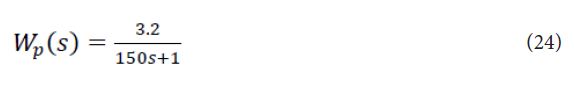
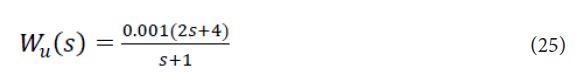
Where 𝑊𝑝(𝑠) denotes the weight related to the performance and 𝑊𝑢(𝑠) denotes the weight related to the control signals. Subsequently, the relationships were thoroughly examined, and the simulation results are presented in the following section.
Robust Controller Results
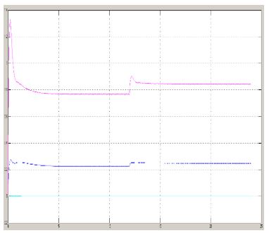
First, the nominal performance, robust stability, and robust performance are validated following the simulation to ensure that the conditions outlined above are met (Figure 3). As shown in Figure 3, they were all less than one and thus met the robustness criteria. The network's power balance is presented in Figure 4, which is not established during the early hours due to the same network delay. The response fluctuates due to the same delays (zeroes to the right of the imaginary axis) that causes undershoot. Figure 5 depicts the magnitude of the control signal.
As can be seen, when the load changes, the control signal must also change in order to maintain network balance. Thus, all of the objectives outlined in this paper for developing robust control were met, and the results indicated that the optimal controller could be simulated through the following step.
Optimal Controller Results
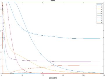
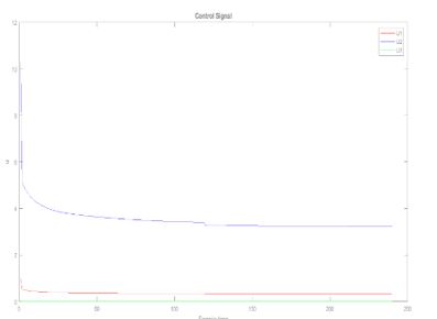
Following the simulation and application of the control signal obtained in the preceding steps, the following figures illustrate the simulation result:
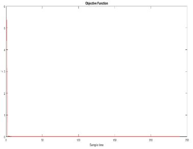
As shown in Figure 6, the system states are between 0 and 1, indicating that the condition is satisfied. On the other hand, several states have changed in response to changes in the load, demonstrating the simulation's accuracy. As illustrated in Figure 7, the control signals are within the desired band, and when the load changes, the control signal changes as well, indicating that an attempt at power balance has been made. Additionally, Figure 8 depicts the cost function, which has been reduced to zero.
As can be seen, the difference between load and production power was significant during the first hour. However, after two to three hours, the difference between production and consumption power was negligible, indicating that the controller performs its function correctly while explaining the difference during the early hours. Furthermore, it is dependent on the starting conditions, which can be adjusted to balance them during the primary hours; however, because the objective is to evaluate the controller's performance, these initial conditions have been considered. The model's delay is another explanation for the initial hour disparity. The data obtained show that all objectives were met.
Conclusion
Microgrids receive considerable attention today due to their critical role in the power grid and are subjected to many optimization and control tasks. One of the most critical aspects of any network is its resistance to uncertainty. Furthermore, because power grids have a communication delay between power plant units, this delay should be modeled in the network to ensure that the results are more accurate and realistic. In addition, achieving the optimum result is another goal that must be achieved. Thus, this paper aims to design robust and optimal controllers by considering the delay in the simulated model, with the results indicating that the optimum outcome is achievable despite the delay and uncertainty. This method can also be replicated in large-scale distributed networks, which will likely be implemented in the near future.
References
- S. Iqbal, A. Xin, M. U. Jan, M. A. Abdelbaky, H. U. Rehman, S. Salman, S. A. A. Rizvi, " Aggregation of EVs for Primary Frequency Control of an Industrial Microgrid by Implementing Grid Regulation & Charger Controller," IEEE, 2020.
- S. Iqbal, A. Xin, M. U. Jan, S. Salman, S. A. U. M. Zaki, H. U. Rehman, M. A. Abdelbaky, "V2G Strategy for Primary Frequency Control of an Industrial Microgrid Considering the Charging Station Operator", MDPI, 2020.
- Y. Arya, "Effect of electric vehicles on load frequency control in interconnected thermal and hydrothermal power systems utilising CF-FOIDF controller," IET, 2020.
- A. Safari, F. Babaei, M. Farrokhifar, "A Load Frequency Control Using a PSO-based ANN for Micro-Grids in the Presence of Electric Vehicles," International Journal of Ambient Energy, 2018.
- A. Naderipour, Z. Abdul-Malek, I. F. Davoodkhani, H. Kamyab, R. R. Ali, " Load-Frequency Control in an Islanded Microgrid PV/WT/FC/ESS using an Optimal Self-Tuning Fractional-Order Fuzzy Controller," Research Article, 2021.
- F. Banis, D. Guericke, H. Madsen, "Load–frequency control in microgrids using target-adjusted MPC," IET, 2019.
- J. Hu, P. Bhowmick, "A Consensus-based Robust Secondary Voltage and Frequency Control Scheme for Islanded Microgrids," Preprint submitted to International Journal of Electrical Power and Energy Systems, 2020.
- J. Huang, X. Zhang, A. Zhang, P. Wang, " Comprehensive Coordinated Frequency Control of Symmetrical CLLC-DC Transformer in Hybrid AC/DC Microgrids," IEEE, 2019.
- Masoud Dashtdar, Majid Dashtdat, "Voltage and Frequency Control of Islanded Micro-grid Based on Battery and MPPT Coordinated Control," MJECE, 2020.
- W. Yuan, Y. Wang, Z. Chen, "New Perspectives on Power Control of AC Microgrid Considering Operation Cost and Efficiency," IEEE, 2021.
- F. S. Ismail, "DC Microgrid Planning, Operation, and Control: A Comprehensive Review," IEEE, 2021.
- W. Ali, A. Ulasyar, M. U. Mehmood, A. Khattak, K. Imran, H. S. Zad, S. Nisar, "Hierarchical Control of Microgrid Using IoT and Machine Learning-Based Islanding Detection," IEEE, 2021.
- J, Zhou, H. Sun, Y. Xu, R. Han, Z. Yi, L. Wang, J. M. Guerrero, "Distributed Power Sharing Control for Islanded Single-/Three-Phase Microgrids With Admissible Voltage and Energy Storage Constraints," IEEE, 2021.
- P. P. Dey, D. C. Das, A. Latif, S. M. S. Hussain, T. S. Ustun, "Active Power Management of Virtual Power Plant under Penetration of Central Receiver Solar Thermal-Wind Using Butterfly Optimization Technique," Sustainability, 2020.
Article Information
Research Article
Received Date: March 05, 2025
Accepted Date: March 23, 2025
Published Date: March 30, 2025
Journal of Energy and Renewable Resoures
Volume 1 | Issue 1
Citation
Mehdi Soleymanizadegan (2025) Design of Robust and Optimal Controllers for Microgrid Power Control with Delays Between Power Plants. J Energy Renewable Resour 1: 103
©2025 Mehdi Soleymanizadegan. This is an open-access article distributed under the terms of the Creative Commons Attribution License, which permits unrestricted use, distribution, and reproduction in any medium, provided the original author and source are credited.