

Review Article
Volume-1 Issue-1, 2025
Point-Like Neutron Monitor for the High-Flux Nuclear and Thermonuclear Reactors
-
Received Date: March 01, 2025
-
Accepted Date: March 19, 2025
-
Published Date: March 26, 2025
Journal Information
Abstract
The flow gas radiochemical method is proposed to be used for monitoring of neutron flux in high-flux nuclear reactors, such as the PIK of the St. Petersburg Institute of Nuclear Physics named by B.P.Konstantinov. A feature of the technology is the spatial separation of neutron detection and their registration by means of transporting the resulting radioactive gas 37Ar - a product of a nuclear reaction in the core with the help of transport gas He to a remote and protected decay counter. In this formulation, the technology makes it possible to drastically reduce the background load from γ-quanta and other competing processes. To place a detector ampoule in a narrow technological channel of a PIK nuclear reactor, its dimensions must be very small. A small amount of the active substance in the detector ampoule, in addition, will reduce the decay count and the load on the readout electronics. In fact, the limiting dimensions of the detector ampoule can be considered as "pointlike" and such ampoules can be used to obtain a spatial distribution of the neutron flux across the core of a high-flux nuclear reactor.
Key words
High-Flux Nuclear; Thermonuclear Reactors; Point-Like Monitor
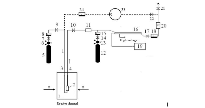 |
| Figure 1: Scheme of the gaseous path of a flowing radiochemical neutron monitor. Designations in the diagram: 1- reactor channel, 2 - detector microampule, 3 - input He tube, 4 - output tube for the flow of the mixture of He with radioactive argon, 5, 12 - cylinders of He and quenching agent CH4 , respectively, 6,13 - pressure regulators, 7,9, 10, 14, 17, 21, 22 - gas flow regulators, 8, 15, 18,24 - flow meters, 11 - getter, 16 - proportional counter, 19 – readout electronics, 20 - nitrogen trap, 23 – compressor. |
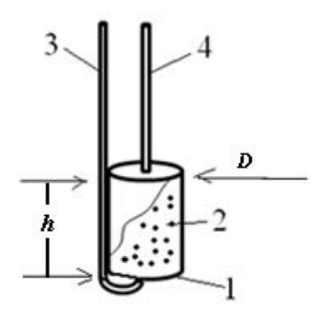 |
| Figure 2:Design of the detector ampoule of the neutron monitor. The designations on the scheme: 1 - the ampoule case, 2 – the calcium oxalate powder, 3 - the transport gas He supply tube, 4 - the output flow of the mixture of He with a radioactive argon. |
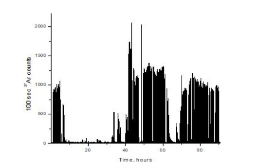 |
| Figure 3:An illustration of flow gas radiochemical detector for neutron monitoring [10] at the RADEX facility in the Institute for Nuclear Research of the Russian Academy of Sciences [15]. Dark areas correspond to the presence of a neutron flux due to interacting of proton beam with the neutron target, light areas correspond to its absence. As for limitation of this method it is needed to note that on the amplitude spectrum of signals from proportional counter, in addition to the characteristic spectrum of Auger electrons from 37Ar decays, a significant (40% of the spectrum area) contribution was also observed from the continuous spectrum from the β-decay of 41Ar formed by the reaction: 44Са (n,α ) 41Ar with a reaction threshold of 5 MeV. The content of 44Ca in the natural mixture is 2.06%. The half-life of 41Ar is T1/2=1.83 hours, and the ratio Т1/2(37Ar) / Т1/2(41Ar) =459. Therefore, a contribution from the decay of 41Ar appeared in the hard spectrum of the RADEX neutron target. In the case of a thermal reactor, this contribution is strongly suppressed due to the high threshold of the corresponding reaction. |
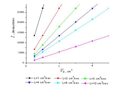 |
| Figure 4: The family of dependences of the decay count rate I vs. the volume of the detector ampoule Va for various transport gas flow rates L in the active core of PIK reactor. |
Introduction
Commissioning of the high-flux nuclear reactor PIK on the territory of Petersburg Nuclear Physics Institute named by B.P.Konstantinov with a maximum thermal power of 100 MW and a maximum neutron flux density of up to 5×10¹⁵neutron cm-2 sec-1 [1], as well as the international thermonuclear reactor ITER with a neutron flux density of up to 1.5×10¹⁴ neutron cm-2 sec-1 [2] will require the use of radiation-resistant, compact, simple in design and operation neutron flux detectors. Although at present there are peripheral neutron detectors, mainly based on ionization chambers and position-sensitive detectors [3], there are still no neutron flux monitors in the reactor core center. The problems of their placement are associated with extremely high neutron fluxes, which overload the readout electronics, background loading from γ - quanta, as well as high temperatures in the vicinity of the core. The solution to this problem may be the placement in the center core of high-flux nuclear reactors, such as PIK (Russia) [4], HFR (France) [5], HFIR (USA) [6], FRM (Germany) [7], as well as near active zone of the international thermonuclear reactor ITER [8] flow gaseous radiochemical neutron flux monitors [9-13]. The flow gas radiochemical monitor uses the property of free release of the inert radioactive gas 37Ar, formed in the nuclear reaction 40Са(n,α)37Ar, from the crystal lattice of calcium oxalate CaC2O4. The inert radioactive gas 37Ar formed in the detector ampoule is transported by the He carrier gas to a remote proportional gas counter of the flow type, where the decay rate of the radioactive inert gas nuclei is measured, which is uniquely related to the neutron flux density in the core. The advantage of the proposed neutron monitor is a small amount of CaC2O4 active substance and small detector sizes required to detect high neutron fluxes in the core center, as well as a relatively high temperature of CaC2O4 decomposition, which is about 350ºС. The remote location and shielding of the decay counter allows to get rid of the background of γ - quanta.
Monitor Design
The scheme of the gas path of the radiochemical neutron monitor is shown in Figure 1. The difference from the schemes of the gas path used in [9–13] consists in the design of microampoule 2 filled with powdered calcium oxalate. As for small detector ampoules the manufacturing process is rather simple: small aluminum ampoule is welded with the aluminum input and output tubes. The ends inside the ampoule are closed with a non-combustible cloth to avoid calcium oxalate powder spilling out through the supply tubes of the gas path. A general view of the microampule design is shown in Figure 2. Inlet 3 and outlet 4 tubes of the helium path have an outer diameter of 2 mm and an inner diameter of -1 mm. The average size of calcium oxalate crystallites is about 30-50 microns. Another new element scheme is a nitrogen trap 20 at the outlet of the gas mixture from the counter 16 to the atmosphere aiming to purify the transport gas from radioactive argon impurities. Purification of transport gas helium based on the difference in the boiling temperatures of helium and argon.
The dotted line in Figure 1 shows the possibility of returning spent He, purified from radioactive gas impurities and a quenching agent, back to the gas path. This option is necessary for high gas flow and long-term operation of the monitor due to the high cost of transport gas He. The design of the microampule Figure 2 is chosen so that it freely enters the serviced channel of the nuclear reactor. In the case of the PIK reactor, this is the central experimental channel with a neutron trap ~8 cm in diameter [14]. The gas proportional neutron counter is an all-quartz sealed construction. The detector cathode is pyrographite layer, obtained by decomposition of isobutane at a temperature of~ 950°C. The thickness of the pyrographite layer is ~1 µm. After deposition of the layer some excess pyrographite where it is not needed is removed by burning in oxygen flow. Contact with the cathode is provided through a side capillary branch with a pyrographite inner coating. Molybdenum foil with the thickness of 10 μm, and width of 1 mm welded into quartz glass provides an electrical contact with inner coating. A similar foil acts as an anode output contact. The anode itself is a tungsten wire with a diameter of 20 microns. Detector dimensions are as follows the length is about 250 mm; internal diameter is about 18 mm.
The anode resource is the erosion of the anode wire in a gas discharge, which is difficult to estimate, but if we take as a basis the usual value for Geiger counters of 1012-13 operations with a charge per operation of 10-6 Coulomb, we get a charge resource g = 106 Coulomb. In our case, when charging for one operation gf = 106x104 = 1010e = 10-9 Coulomb, we get the number of operations n = 106 /10-9 = 1015 pulses. At the counting rate nf = 106 sec-1, the lifetime of the counter τc = 1015/106 = 109 sec ~ 30 years, which is quite acceptable.
Gas amplification is an increase in the number of free charges in the volume of the detector due to the fact that primary electrons on their way to the anode in high electric fields acquire energy sufficient for impact ionization of neutral atoms of the detector's working medium. The new electrons that have arisen in this case, in turn, have time to acquire energy sufficient for impact ionization. Thus, a growing electron avalanche will move towards the anode. This "self-amplification" of the electron current (gas amplification factor) can reach 103-104. This mode of operation corresponds to a proportional counter (chamber). The name reflects the fact that in this device the amplitude of the current pulse (or the total collected charge) remains proportional to the energy spent by the charged particle on the primary ionization of the detector medium. When using the reaction 40Са(n,α)37Ar on helium, one can expect the energy resolution of the detector to be at the level of (2х106/20)-1/2~3•10-3. Currently, counters are produced in single copies. The cost of one counter is about $1000.
An example of using the described technique for monitoring of neutron flux on the RADEX neutron target [15] is shown in Figure 3. The use of a neutron monitor in the center of the active zone is very useful in terms of obtaining information about the temporary behavior of a neutron source, as well as on the degree of burnout of the fuel. In addition, the indications of the neutron monitor in the center of the active core will allow comparing the data of neutron monitor with the corresponding data of other neutron detectors located in experimental channels.
Count rate in the reactor channel
To evaluate the advantages of a radiochemical neutron monitor in the reactor core, it is necessary to determine the decay count rate of the proportional counter 16 in Figure 1 In the stationary mode of ampoule irradiation (with a constant neutron flux Ф and a constant flow rate of the carrier gas LHe), all newly formed activity above the equilibrium level is removed from the volume of the ampoule by the flow of carrier gas. Therefore, the count rate of the decays in a mixture of radioactive gas with a carrier gas is related to the neutron flux by the known relationship [9]:
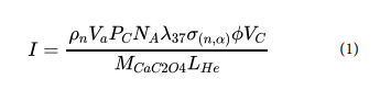
In expression (1), the following notation is used: I is the number of decays per second of a radioactive 37Ar in the counter, ρn = 1 g/cm3 is the density of bulk calcium oxalate powder in an ampoule, Va , Vc is the working volume in cm3 of the ampoule and counter, respectively, Рс is the pressure in the counter in physical atmospheres, NA is the Avogadro number, λ37 = 2.3×10⁻⁷ sec-1 is the decay constant of the 37Ar, (n,α) = 2.0×10⁻²⁶ cm2 is the nuclear reaction cross section averaged over the neutron spectrum for the reaction 40Са( n,α)37Ar , - the neutron flux density (neutron/cm2/sec), MCaC2O4 = 128 – the molecular weight of calcium oxalate, LHe – the consumption of transport gas He in cm3/sec. Expression (1) is applicable when Va/LHe < 0.8 MeV in the center of active core of the PIK reactor are shown in Figure 4.
As can be seen, the count rates for radioactive argon decays are significantly lower than the maximum currently achieved level of 125 kHz [16]. With an increase in the transport gas flow rate L and a decrease in the volume of the detector ampoule Va, the decay counting rate decreases. These circumstances are favorable for registration of record neutron fluxes in the core centers of high-flux nuclear reactors, and these fluxes can be measured by extremely small, literally "pointlike" detecting ampoules. For example, with a detector ampoule diameter D and h height both equal to 1 cm, the volume of the ampoule will be ~1 cm3, while it can be easily moved in the experimental channel of a high-flux nuclear reactor PIK. Then, as can be seen from Figure 4 and relation (1), at a transport gas flow rate L= 1 cm3/sec, the decay count rate will be 27 kHz. The length of the gas path is the distance from the location of the neutron detector ampoule in the core to the location of the proportional decays counter. In this case, the signal delay time due to movement along the gas path with a length of LT =1000 cm through tubes with an internal diameter d=0.1 cm will be τ~d2LT/4L~8 sec. With an increase in the flow rate of transport gas, the delay time decreases. This is favorable for closing to the real time picture of neutron flux. Reducing the dimensions of the detector ampoule is limited only by the possibility of mechanical fastening of the supply pipes. It is proposed to use stainless steel or aluminum alloy as the material of the detector ampoule and tubes of the gas path, the last one is less susceptible to activation.
Burnout of CaC2O
At least one factor determines the life of the detector - CaC2O4 burnup. Let's consider it in more detail. Burnout of CaC2O4 will take place due to nuclear reaction. Let us estimate the fluence up to burnout. Let's fix the share of burnt-out active substance = 10%, then =Фt =2×10-26Фt, where t is time of neutron irradiation. Then we get that the value of the neutron fluence Фt will be about 0.5×1025 n/cm2. This corresponds to the exposure time t~109 sec. or about 27 years
Discussion
The radiochemical gas neutron monitor is a fundamentally new neutron detector with a simple design that does not contain any mechanical elements. The detecting ampoule is filled with a powdered active substance calcium oxalate CaC2O4 with a high decomposition temperature of 350°C. The inert radioactive gas 37Ar formed as a result of the (n, α) nuclear reaction easily leaves the crystal structure of calcium oxalate and does not interact with the elements of the gas path. The decay counter is located remotely behind the biological shield and is connected to the detector ampoule by a gas path. This solution can significantly reduce the background loading of the counter. Background processes are also reduced by using a specific nuclear reaction 40Са (n, α) 37Ar according to the “key and lock” principle. Thus, in the active zone of a nuclear reactor there are metal (aluminum or stainless steel) ampoule and tubes of the gas path, calcium oxalate powder, as well as transport inert gas helium. The relatively high rate of 37Ar decays makes it possible to drastically reduce the size of the detecting ampoule to ~1 cm3 and place it freely, for example, in the central experimental channel of the PIK reactor with a diameter of ~80 mm. In this case, it is possible to measure the neutron flux at several points along the channel diameter (about 8 points), as well as along the entire channel along its height. The spatial resolution of the detector is about 1 cm, which is not available for other types of detectors. For example, the minimum dimensions of a fission chamber are 5 cm in diameter and 30 cm in length [17]. It is problematic to place fission chambers in the channel of a high-flux reactor due to the high background, the instability of electrical contacts, and also because of the too large cross section for the interaction of neutrons with fissile material (thousands of barns) and the high decay rate when superimposition of spontaneous alpha decays occurs. The use of fission chambers with very little fissile material gives a very low current under high background conditions. The cross section for the interaction of 40Ca with neutrons is about 0.2 barns, which makes it possible to control the size and sensitivity of the detector over a wide range. The detector has its drawbacks, such as a time delay due to the movement of the transport gas along the gas path, low neutron detection efficiency, which is obtained from a comparison of the decay rate inside the ampoule FσNat and the incident flux FSamp of about 0.16%, where F is the neutron flux density in the channel, σ is the reaction cross section, Nat is the number of calcium oxalate atoms in the ampule ~1023, Samp is the surface area of the ampule. The resulting accuracy is also a characteristic value for ionization chambers. This detector cannot be used for operational control of a nuclear reactor; however, it allows obtaining information on such processes in the center of the core as the distribution of the neutron flux density along the radius and length of the neutron channel, fuel burnup in the central fuel elements. Since the PIK, HFR, HFIR, and FRM reactors are water-- cooled with boiling, the temperature in the central zone does not exceed 200°C, and the temperature in the ITER working chamber is 150-200°C [18], CaC2O4 powder can be used without degradation. The difference in the design and properties of the high-flux reactor monitor and the RADEX neutron target driven by the INR RAS proton accelerator (see Ref. [10], which is added to the caption of Fig. 3) is an unprecedented high neutron flux density of 5·1015 neutron/cm2/sec in the first case compared with the second case (about 108-9 neutron /cm2/sec). If in the first case a similar detector was used, as in the second case, then the decay count rate would be prohibitively high from the point of view of its processing by electronics having in mind that 125 kHz is the maximum possible information processing speed for modern electronics. Therefore, the size of the detector ampoule can be significantly reduced, which also made it possible to obtain a point-- like detector. In addition, by changing the transport gas flow rate, it becomes possible to control the count rate and the detection efficiency in different reactor operating modes. Another difference of the detector compared to the previous version is the use of a nitrogen trap to clean the spent helium and reuse it. Purification is carried out due to the difference in the boiling points of nitrogen and impurities. The accuracy of determining the rate of decays of 37Ar with an ampoule volume of ~1 cm3 and a helium flow rate of 3 cm3/sec can be estimated as 1/√I ~ 0.63% (see Fig.4). The neutron monitor operates in the mode of a proportional counter with an applied voltage of ~1250 V and a gas gain of ~1000, the gas pressure in the counter is ~1 atm. The dead time of the counter is ~10-5sec, so the counting rate without imposing pulses can be ~100 kHz. As can be seen from Fig. 4, this condition is satisfied even for a small consumption of transport gas and the volume of the ampoule.
As for the limitations of the method the time delay can be mentioned which is discussed in the text of the paper. Another limitation is aluminum alloy behavior in high flux reactor. However 40 years of experience in the operation of the SM-2 reactor shows that structural alloys exhibit satisfactory radiation resistance up to a neutron fluence of 1023 cm-2. The limit of the range of neutron energies is defined by the threshold of (n, α) nuclear reactions. As for background radiation the counter is placed inside the biological shielding remote from the active zone of nuclear reactor. It seems there are no limitations with scaling up the technology for use in larger number reactors.
Conclusion
The flow gas radiochemical method is proposed to be used for monitoring of neutron flux in high-flux nuclear reactors, such as PIK of the St. Petersburg Institute of Nuclear Physics named by B.P.Konstantinov.
The spatial separation of neutron detection and their registration gives rise to subsequent decrease of background load from γ-quanta and other competing processes. The technology to be used makes it possible to drastically reduce the dimensions of detecting ampoule up to “pointlike” shape.
"Pointlike" dimensions of detecting ampoules are favorable for registration of record neutron fluxes in the core centers of high-flux nuclear reactors at the acceptable count rate of readout electronics.
Acknowledgement
I express my appreciation and my sincere gratitude to my untimely departed friend Viktor Yants. The theme of this and our other joint works was largely initiated by Viktor. Bright memory!
References
- Kovalchuk MV, Smolsky SL, Konoplev KA (2021) Research reactor PIK. Crystallography, 66: 184-190.
- Claessens M (2020). ITER: the giant fusion reactor. Cham, Switzerland: Springer International Publishing.
- Krivshich A, Ilyin D, Hall-Wilton R (2020). Strategy of Equipping the PIK Reactor Experimental Stations with Detection Systems. IAEA TECDOC SERIES 251.
- Kovalchuk MV, Voronin VV, Grigoriev SV, Serebrov AP (2021). Instrument base of the PIK reactor. Crystallography 66: 191-213.
- High-flux Reactor at Petten (1961). Nature 192: 708.
- Rush JJ (2015). US Neutron Facility Development in the Last Half-Century: A Cautionary Tale. Phys. Perspect 17: 135-55.
- Axmann A, Böning K, Rottmann M (1997). FRM-II: The new German research reactor. Nuclear engineering and design 178: 127-33.
- Hassanein A, Sizyuk V (2021). Potential design problems for ITER fusion device. Scientific Reports 11: 1-11.
- Abdurashitov DN, Koptelov EA, Lebedev SG, Yants VE (2004). A gaseous radiochemical neutron monitor. Instruments and Experimental Techniques 47: 294-9.
- Lebedev SG, Akulinichev SV, Iljinov AS, Yants VE (2006). A gaseous radiochemical method for registration of ionizing radiation and its possible applications in science and economy. Nuclear Instruments and Methods in Physics Research Section A: Accelerators, Spectrometers, Detectors and Associated Equipment 561: 90-99.
- Lebedev SG, Yants VE (2019). Radiochemical detector of spatial distribution of neutron flux density in nuclear reactor. Nuclear Instruments and Methods in Physics Research Section A: Accelerators, Spectrometers, Detectors and Associated Equipment 916: 83-86.
- Lebedev SG, Yants VE (2021). State-of-the-art progress of gaseous radiochemical method for detecting of ionizing radiation. Nuclear Engineering and Technology 53: 2075-83.
- Lebedev SG, Yants VE (2019). High-speed gas neutron detector for thermometry of thermonuclear plasma. Nuclear Instruments and Methods in Physics Research Section A: Accelerators, Spectrometers, Detectors and Associated Equipment 945: 162633
- Петров ЮВ, Ерыкалов АН, Котова ЛМ, Онегин МС, Сахновский ЭГ (2003). Реактор ПИК-2 с пониженным расходом высокообогащенного урана. Атомная энергия 95: 261-70.
- Koptelov EA, Lebedev SG, Sobolevsky NM, Strebkov YS, Subbotin AV (2002). Radiation damage parameters for modelling of FRM irradiation conditions at the RADEX facility of INR RAS. Journal of nuclear materials 307: 1042-6.
- Chiesi L, Kejik P, Janossy B, Popovic RS (2000). CMOS planar 2D micro-flux gate sensor. Sensors and Actuators A: Physical 82: 174-80.
- Bell Z, Harrison M, Holcomb D, Britton C, Bull N (2012). Materials Selection for a High Temperature Fission Chamber ORNL/LTR-2012/331, Oak Ridge National Laboratory.
- Investigation of the Effect of Heating on the Formation of Carbon Films on Diagnostic Mirrors KYu Vukolov, LS Danelyan, VV Zatekin, SN Zvonkov, VS Kulikauskas, AA Medvedev et al. (2008). Journal of Surface Investigation Xray, Synchrotron and Neutron Techniques 2: 264.
Artcle Information
Review Article
Received Date: March 01, 2025
Accepted Date: March 19, 2025
Published Date: March 26, 2025
Journal of Nuclear Science and Technology Updates
Volume 1 | Issue 1
Citation
S G Lebedev (2025) Point-Like Neutron Monitor for the High-Flux Nuclear and Thermonuclear Reactors. J Nucl Sci Tech. vol 1: 102
Copyright
©2025 S G Lebedev. This is an open-access article distributed under the terms of the Creative Commons Attribution License, which permits unrestricted use, distribution, and reproduction in any medium, provided the original author and source are credited.

doi: jnst.2025.1.102