

Research Article
Volume-1 Issue-2, 2025
Modeling and Simulation Analysis Method of Compressed Air Energy Storage System
-
Received Date: August 02, 2025
-
Accepted Date: August 20, 2025
-
Published Date: August 27, 2025
Journal Information
Switch to Full Text Menu
Abstract
The International Atomic Energy Agency (IAEA) adopted in 2007 and approved officially in 2008, the document entitled “International Atomic Energy Agency Code of Practice for the Radiation Sterilisation of Tissue Allografts” (also known as the IAEA Code of Practice) after several years of intensive work carried out by a group of international experts under the supervision of the IAEA Secretariat. The current IAEA Code of Practice text sets out the main requirements to ensure that the radiation sterilization of tissues produces high-quality sterilized tissues suitable for safe clinical use in specific medical treatments, such as skin burns and bone cancer, among others. The IAEA’s main contribution to the process of human tissue sterilization is the development of a specific technique for tissue sterilization and a unique guideline for the safe use of this technique in several IAEA member states from different regions.
Key words
Ionizing Radiation; Sterilization of Tissues; IAEA Code of Practice; IAEA; Radiation Dose; Tissue Banks
|
No |
Name |
Value |
Units |
|
1 |
Compression ratio |
124 |
—— |
|
2 |
Compressor series |
4 |
—— |
|
3 |
Compression ratio single class |
3.34 |
—— |
|
4 |
The flow rate of the stored gas |
0.46 |
kg/s |
|
5 |
Isentropic efficiency of the compressor |
0.81 |
—— |
|
6 |
Environment temperature |
298 |
K |
|
7 |
Environmental pressure |
0.1 |
MPa |
|
8 |
Efficiency of heat exchanger |
0.9 |
—— |
|
9 |
Initial temperature of heat exchange fluid |
293 |
K |
|
10 |
Ultimate pressure of the air storage chamber |
10 |
MPa |
|
11 |
Volume of the air storage chamber |
100 |
m3 |
|
12 |
Number of turbine classs |
3 |
—— |
|
13 |
Pressure ratio per class of expansion |
25 |
—— |
|
14 |
Gas flow rate during energy release |
2.41 |
kg/s |
|
15 |
Expansion ratio single class |
3.42 |
—— |
|
1 |
2 |
3 |
4 |
5 |
||
|
simulation result |
298 |
314.36 |
311.90 |
310.89 |
310.63 |
|
|
Actual value |
298.00 |
318.00 |
318.00 |
318.00 |
318.00 |
|
|
Onlet temperature of compressor(K) |
simulation result |
463.68 |
443.18 |
434.72 |
432.62 |
387.65 |
|
Actual value |
416.00 |
418.00 |
422.00 |
419.00 |
390.00 |
|
|
Temperature after heat exchange(K) |
simulation result |
314.36 |
311.90 |
310.89 |
310.63 |
305.24 |
|
Actual value |
318.00 |
318.00 |
318.00 |
318.00 |
303.00 |
|
|
1 |
2 |
3 |
4 |
5 |
Total |
||
|
Shaft power(kW) |
Calculated value |
76.59 |
59.55 |
56.75 |
56.36 |
35.48 |
284.73 |
|
Actual value |
76.73 |
59.36 |
57.66 |
57.43 |
36.26 |
287.44 |
|
|
Relative error(%) |
0.18 |
0.32 |
1.58 |
1.86 |
2.15 |
0.94 |
|
|
Classs |
1 |
2 |
3 |
Total |
|
|
Shaft power(kW) |
simulation result |
-145.20 |
-188.07 |
-250.12 |
-583.39 |
|
Actual value |
-149.00 |
-191.00 |
-246.00 |
-586.00 |
|
|
Relative error(%) |
2.55 |
1.53 |
1.67 |
0.45 |
|
 |
| Figure 1:The model of compression |
 |
| Figure 2:The model of expansion |
 |
| Figure 3:The model of air storge chamber |
 |
| Figure 4:The system model of CAES |
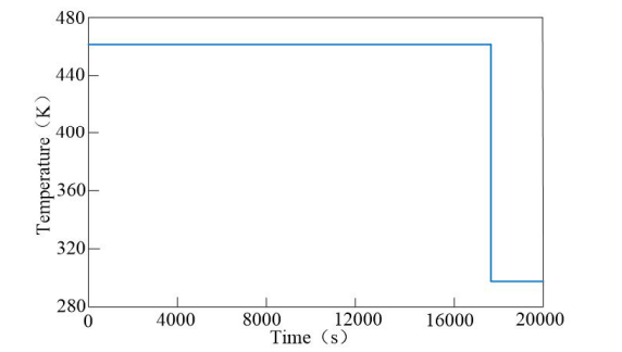 |
| Figure 5:Outlet gas temperature of compressor class 1 |
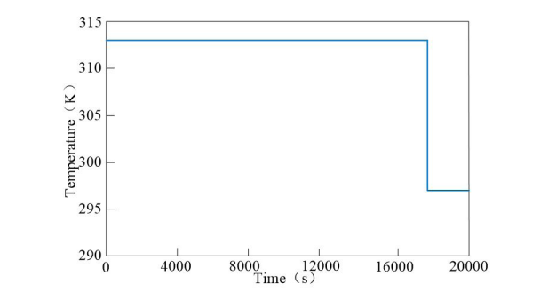 |
| Figure 6:Outlet gas temperature of first class heat exchanger |
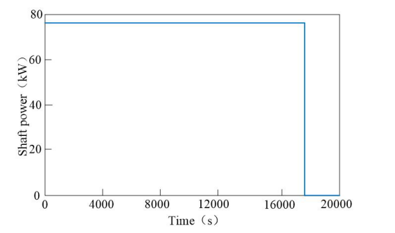 |
| Figure 7:The shaft power of the first class compressor. |
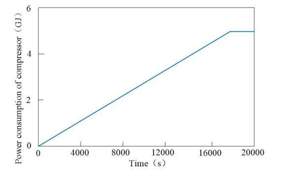 |
| Figure 8:The change of compression power consumption |
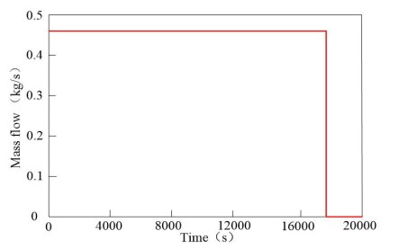 |
| Figure 9:The mass flow of gas entering the gas storage chamber |
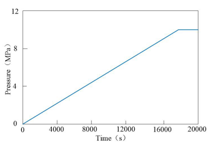 |
| Figure 10:Gas pressure in the gas storage chamber |
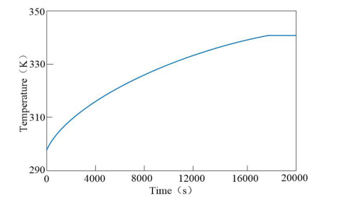 |
| Figure 11:The temperature change in the gas storage chamber |
Introduction
Energy storage technology came into being in the course of the evolution of renewable energy such as solar energy and wind energy. It stores electric energy by some means or medium, and releases energy and discharges when there is power demand. It has unique characteristics of time-sharing energy storage and release, and can realize the role of "peak cut" and balancing power load. Compressed air energy storage (CAES) technology has obvious advantages among many energy storage technologies. It has large generating capacity and the most proven technology. Compared with other forms of energy storage technology, it has the characteristics of high efficiency, long service life, large storage capacity and small investment [1-3]. The advanced adiabatic compressed air energy storage system (AA-CAES) introduces the heat storage technology on the basis of the traditional CAES system. It uses the heat storage medium to recover the compression heat generated in the compression stage, and stores the high-temperature heat storage medium. During the energy release stage, the high-temperature heat storage medium preheats the high-pressure air through the heat exchanger. The heat storage system replaces the supplementary combustion of the combustion chamber to heat the air, so as to reduce the energy loss of the system and improve the efficiency. Jia Mingxiang built a static CAES system model[4]. He Qing proposed variable compression ratio in the compression process of CAES system and studied the compression ratio of CAES expansion process[5-6].
A dynamic model of the compressed air system consisting of compressor, air storage chamber, expander and heat exchanger is established. Compared with the static model that can only display results in the past, this model can simulate the parameter changes in the working process of the energy storage system. Through the simulation of ticc-500 energy storage power plant, the accuracy of the model is verified.
PRINCIPLE OF CAES SYSTEM
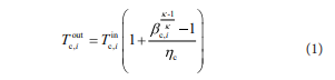
CompressorWhen the compression is underway, the compressed medium in the compressor can be regarded as adiabatic change because the flow rate is fast and there is no time to dissipate heat. Therefore, the working medium temperature at the outlet [7]:
here  is the gas temperature after
the stage i of compressor,
is the gas temperature after
the stage i of compressor,
 is the inlet gas temperature of the
class i compressor,
is the inlet gas temperature of the
class i compressor, is the pressure ratio of the class i. is the adiabatic exponent,
 is is the adiabatic efficiency of
the compressor.
is is the adiabatic efficiency of
the compressor.
The compressor power consumption of unit mass working medium after multistage compression is
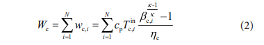
where cp is the constant pressure heat capacity ratio.
Heat exchanger in the process of energy storageThe purpose of heat exchange in the compressed working medium stage is to make the stored working medium temperature lower. Containers with the same volume can store more working medium, and the exchanged heat can improve the work capacity and system efficiency in the working medium release work stage. In the heat exchanger, its efficiency is defined as [8]:
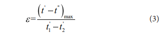
Where,  is the larger value of
low-temperature medium
medium or high-temperature medium in the temperature difference of
heat exchanger;
t1-t2 is the maximum temperature difference
that can realize heat exchange under ideal conditions.
is the larger value of
low-temperature medium
medium or high-temperature medium in the temperature difference of
heat exchanger;
t1-t2 is the maximum temperature difference
that can realize heat exchange under ideal conditions.
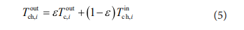
Once the inlet fluid temperature of the class i heat exchanger  is known, the temperature of outlet
gas [9]:
is known, the temperature of outlet
gas [9]:

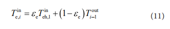
Then the inlet temperature of the class i+1 compressor can be known.
If the difference of heat capacity ratio between heat transfer medium and working medium is not considered, then the temperature of heat transfer medium at the exit of class i heat exchanger is:
The air storage chamber can be regarded as a control volume, so there is [10]:
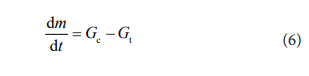
where m represents the mass of air entering the gas storage chamber. Gc means the unit mass flow rate stored into the gas storage chamber, Gt means the unit mass flow gas released from the gas storage chamber. It is known from the law of conservation of energy:
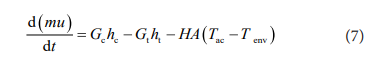
where u represents the internal energy of the stored air, h is the enthalpy, H is the heat exchange coefficient between the gas storage chamber and the external environment, A is the heat exchange area between the gas storage medium and the outside world, Tac is the gas temperature in the gas storage chamber, Tenv represents the external temperature.
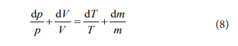
Differentiating the gas equation of state:
Here, the gas storage chamber is considered as a constant volume adiabatic object, that is, the volume of the gas chamber is constant and does not exchange heat with the ambient gas, so the convective heat transfer factor is zero, and the relationship between temperature and pressure in the gas chamber and time can be calculated according to equations (7) and (8):
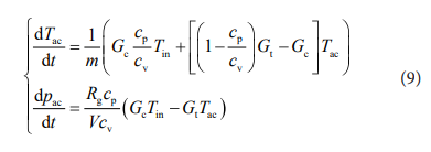
Here, The gas storage chamber is considered as a constant volume adiabatic object, that is, the volume of the gas chamber is constant and does not exchange heat with the ambient gas, so the convective heat transfer factor is zero, and the relationship between temperature and pressure in the gas chamber and time can be calculated according to equations (7) and (8):
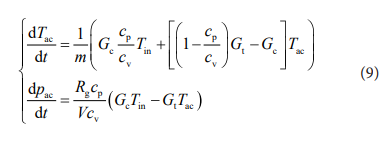
Here cv is the constant volume heat capacity ratio of gas. Pac is the pressure value of stored gas, Tin is gas temperature at the entrance of the gas storage chamber, it is also can be seen the gas temperature at the exit of the last class heat exchanger, Rg is the Perfect Gases. V is the volumetric capacity of the gas storage chamber.
Heat exchanger for the energy release processIn the process of energy release, due to the low temperature of the high-pressure gas released from the gas storage chamber, the heat exchanger will heat up before driving the expander to do work. Therefore, the inlet of the first class heat exchanger is equal to the gas temperature from the gas storage chamber [8-9]:
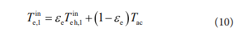
Where  is the inlet medium
temperature of the first class heat exchanger, and the subscript e
represents the energy release process.
is the inlet medium
temperature of the first class heat exchanger, and the subscript e
represents the energy release process.
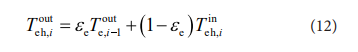
Then the outlet gas temperature after passing through the class i heat exchanger
Expansion is the reverse process of compression. The working medium temperature at the outlet of the class i expander of the expander is [10-11]:
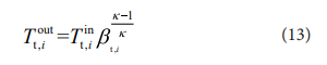
where is the outlet temperature of
the class i turbine, is the inlet
temperature of the class i turbine, k is the isentropic index of the
expansion process
 is the expansion pressure
ratio of the class i turbine.
is the expansion pressure
ratio of the class i turbine.
The work done by the expander to the unit mass gas is:
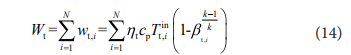
where ηt is the isentropic efficiency of the turbine, cp is the constant pressure heat capacity ratio.
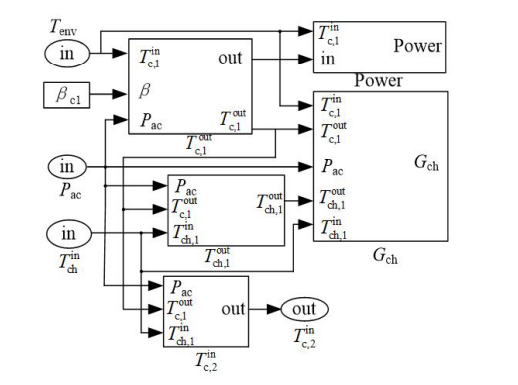
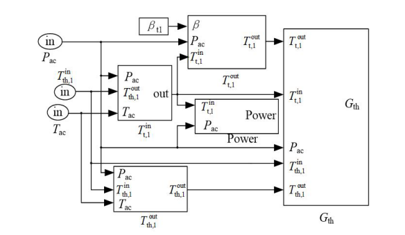
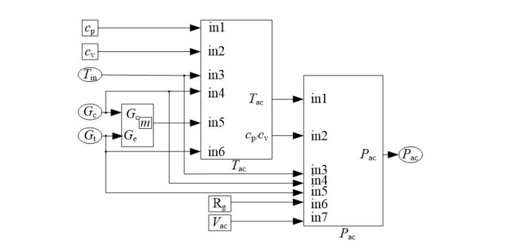
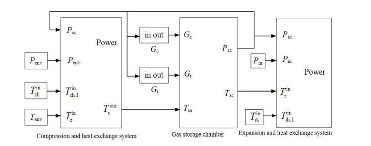
Dynamic model of CAES systemAccording to the mathematical transfer formula of each component of the CAES system, the models of each component are established. The single-class compression model is shown in Fig.1, the air reservoir model is shown in Fig.2, and the single-class expander model is shown in Fig.3. According to the correlation between the components, the dynamic model of the whole CAES system can be built, which can be used to simulate the thermodynamic parameter changes of the compressor, heat exchanger, gas storage chamber and expander during the working process of the system, as shown in Fig.4.
MODEL VALIDATIONThe dynamic model established in this paper can simulate the system only by inputting the parameters of the system. Taking the data of ticc-500 energy storage power station as the calculation parameter , this system is the first AA-CAES platform in China, and the basic parameters of the system are shown in Table 1.
Compression processFig. 5 shows the gas temperature at the outlet of the first class compressor. During the operation of the compressor, because the inlet gas temperature of the first class compressor is constant at the atmospheric temperature of 298K, the outlet temperature of the first class compressor is also basically unchanged, stable at about 463.68k. After the energy storage class is completed, the compressor stops working. Fig.6 shows the gas temperature after passing through the heat exchanger from the first compression class. It can be seen that the gas temperature in the working process is 314.36k, down by about 150k.
Now the gas temperature calculated by simulation and the actual five class compression and five class heat exchange of the system are listed in Table 2. It can be seen that the outlet gas temperature of the first class compressor is the highest, and the outlet gas temperature of the subsequent heat exchanger is also the highest among the five class heat exchangers. According to formula (1), the outlet gas temperature of each class group of the compressor is related to the inlet gas temperature of each class, the pressure ratio of each class and the isentropic efficiency of each class, which is directly proportional to the temperature and pressure ratio, and inversely proportional to the isentropic efficiency. The pressure ratio of the first class is the largest and the insulation efficiency is the lowest, which leads to the highest outlet temperature.
It can be found that there is a deviation between the exhaust temperature of each compression class in the actual operation and the simulation results, because in the simulation process, the gas is analyzed as an ideal gas, and the change of its specific heat with the environment is ignored, which leads to the deviation of the results.
The shaft power of the five class compression class obtained from the simulation and the shaft power of the five class compression class in the actual operation are summarized in Table 3. It can be seen that the error between the shaft power of compressors at all levels calculated by simulation and the actual shaft power of the system is very small, and the maximum error is only 2.15%.
Fig. 7 shows the shaft power of the first class compressor. During the energy storage process, the shaft power of the first class compressor has been maintained at 76.59kw. Fig. 8 shows the change of compression power consumption with time. The shaft power of compressors at all levels is a fixed value during operation, and the total shaft power of five class compression is also unchanged. Therefore, the total power consumption of compression class group is proportional to time and increases linearly with the passage of time. At 17500s, the gas storage process ends, and the power consumption will not increase. The total power consumption of the compressor in the final gas storage stage is 4.981GJ. The total power consumption of system in the actual compression process is 5.174GJ, with an error of 3.73%.
Gas storage chamberFig. 9 shows the change of the mass flow of gas entering the gas storage chamber with time during the gas storage process. The mass flow of gas entering the gas storage chamber after compression at the initial time is 0.46kg/s, and the working condition is stable until 17500s (4.86h). The gas pressure in the gas storage chamber reaches the saturation pressure, and the gas storage stage has been completed. The sign of the completion of the gas storage phase of CAES system is that the gas pressure in the gas storage chamber rises to the limit pressure. In this calculation simulation system, the limit pressure set in the gas storage chamber is 10MPa. Fig.10 shows the change of gas pressure in the gas storage chamber with time during the simulated gas storage process. It is known from Fig. 9 that the mass flow of gas entering the gas storage chamber is constant during the energy storage process. Therefore, the gas pressure in the gas storage chamber increases linearly from the initial pressure of 0.1MPa until it rises to 10MPa in 17500s (4.86h). The system gives a feedback signal, the compressor stops running, and the gas pressure in the gas storage chamber no longer increases.
Fig.11 shows the temperature change of the gas in the gas storage chamber. It can be seen that the temperature gradually increases with time. This is because this modeling regards the gas storage chamber as a constant volume adiabatic model, that is, the volume is fixed, and the gas storage chamber is isolated from the external environment and does not transfer heat outward. Therefore, after entering the gas storage chamber, the compressed high-pressure gas will diffuse to all corners of the container, and the pressure energy will be converted into heat energy, resulting in the rise of temperature. After the completion of the gas storage process, due to the thermal insulation performance of the gas chamber, the gas temperature has remained unchanged and finally stabilized at 340.71k.
The simulated gas storage duration is 17500s (4.86h), while the actual energy storage duration of ticc-500 system is 5h, that is, 18000s, with an error of 2.78%. Because the simulation sets the gas storage chamber as constant volume insulation, the temperature gradually increases with the increase of gas, and the gas temperature in the simulation gas storage chamber is higher than the actual one. According to the ideal gas state equation, for a certain volume of gas, the higher the temperature, the greater the pressure, so the simulation system will reach the saturation pressure in advance.
Expansion processFor the convenience of distinguishing, the shaft power of the compressor is expressed as a positive number, while the shaft power of the expander is expressed as a negative number. During the power generation process of gas expansion, the shaft power of the expander is basically unchanged until the available gas in the gas storage chamber is exhausted, and the expander stops working. Now the shaft power of the expander obtained from the simulation and the shaft power of the expander in the actual operation process are listed in Table 4. It can be seen that the power error of the three-class expansion shaft is within 3%.
A dynamic simulation system of compressed air energy storage is established, which includes compressor, heat exchanger, gas storage chamber and expander. The model can simulate the changes of relevant parameters of compressor, expander and gas storage chamber with time in the working process, and has the advantages of intuition and timeliness.
The dynamic model is verified by TICC-500 energy storage system. Because the gas state is idealized in the simulation process, the calculation results of the simulation model are different from the actual operation data, and the maximum error is reflected in the outlet temperature of each stage of the compressor. In other aspects, such as gas storage time, compressor shaft power and expander shaft power, the error is within 3%. In general, the established model can basically simulate the working process of CAES system truly and effectively, which provides an intuitive and convenient dynamic modeling method for CAES research. Based on the model, more in-depth research can be carried out, and the model can be applied to engineering practice.
References
- Lokhande P.E.,Pakdel Amir,Pathan H.M.,Kumar Deepak,Vo Dai-Viet N.,Al-Gheethi Adel,Sharma Ajit,Goel Saurav,Singh Prabal Pratap,Lee Byeong-Kyu. Prospects of MXenes in energy storage applications[J]. Chemosphere,2022,297.
- Mei Shengwei, Xue Xiaodai, Chen Laijun. Discussion on compressed air energy storage technology and its applica-tion [J]. Southern Power System Technology, 2016, 10(3): 11-15+31+3.
- Qing He, Guoqing Li, Chang Lu, et al. A compressed air energy storage system with variable pressure ratio and its operation control[J]. Energy, 2019, 169.
- Jia Mingxiang. Research on Design Technology of Advanced Compressed Air Energy Storage System[D]. North China Electric Power University, 2018.
- He Qing, Li Guoqing, Du Dongmei. New Compressed Air Energy Storage System with Transformable Pressure Patio and Operation Modes. Automation of Electric Power Systems, 2019, 43(08): 62-68.
- He Qing, Fu Hailun, Kang Haoqiang. Thermodynamic analysis of novel advanced adiabatic compressed air energy storage system with variable pressure ratio. THERMAL POWER GENERATION, 2020, 49(08): 36-42.
- Saravanamuttoo H, Rogers G, Cohen H. Gas Turbine Theory[M]. Prentice Hall, 2001.
- Yang Shiming,Tao Wenquan. Heat Transmission Science[M]. Beijing: Higher Education Press,1998.
- Shah R K, Sekulic D P. Fundamentals of heat exchanger design[M]. New Jersey: John Wiley & Sons, 2003.
- Bejan A. Advanced Engineering Thermodynamics[M]. New York: John Wiley & Sons, 1997.
- Jiang C B . Turboexpanders and recent developments[J]. Cryogenic Technology, 2001..
Artcle Information
Short Communication
Received Date: August 02, 2025
Accepted Date: August 20, 2025
Published Date: August 27, 2025
Journal of Energy and Renewable Resources
Volume 1 | Issue 2
Citation
Morales Pedraza J (2025) The Need to Update the Current International Atomic Energy Agency Code of Practice for the Radiation Sterilization of Tissue Allografts Text. J Energy Renewable Resour 1: 201
Copyright
©2025 Morales Pedraza J. This is an open-access article distributed under the terms of the Creative Commons Attribution License, which permits unrestricted use, distribution, and reproduction in any medium, provided the original author and source are credited.

doi: jerr.2025.1.201